System design for touring, installation, cinema and performance venues Discuss a venue brief
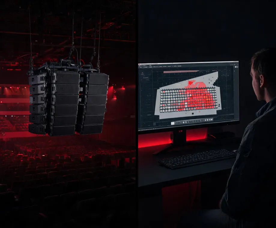
Line array coverage model connected to a real venue
MODELROOM
Applications / evidence path

Martin Audio applications move from audience map to operator handover

A product can publish nominal dispersion and maximum output, but an application must resolve where sound should go, where it should not go, how the system will be supported and how the final result will be checked.

Follow the workflow
A traceable design story

Four decisions link the drawing to the listening position

01

Define the audience and the boundary

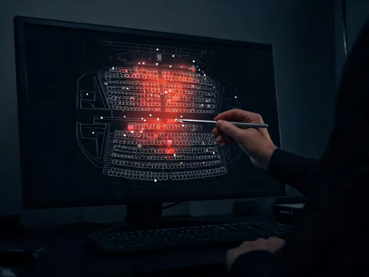
The design brief marks seated and standing zones, balconies, stages, acoustic screens and noise-sensitive areas. It records whether the priority is speech intelligibility, musical impact, cinema reference playback or a flexible combination. Dimensions are labelled surveyed, drawing-derived or estimated so model confidence is not disguised.
02

Compare coverage architectures

Line array, point-source and distributed approaches are evaluated against throw distance, vertical control, sightline, mounting access and required headroom. A longer array may improve directivity but adds weight and visual scale. A distributed system may reduce distance loss but requires more locations, cabling and delay coordination.

03

Translate the concept into a deployable system

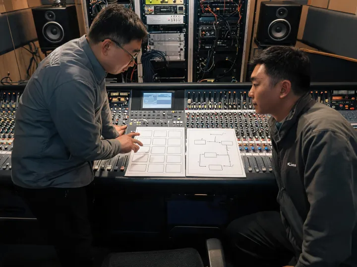
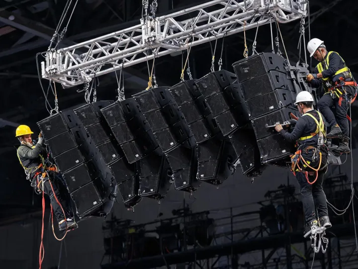
The proposed geometry is checked with qualified mechanical review. Amplifier channel allocation, DSP filters, limiter settings, network monitoring and cable routes are associated with the correct loudspeaker elements. System files receive revision identifiers so commissioning changes are not separated from the drawings they affect.

04

Verify, listen and hand over

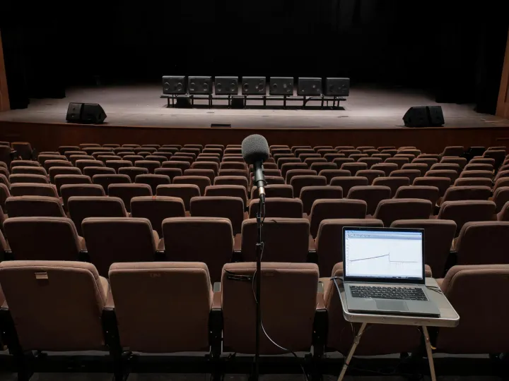
Commissioning begins with wiring, polarity and gain structure before tonal decisions. Calibrated measurements at named positions test arrival time, zone transitions and response trends. Listening with representative program material follows. The final record includes test conditions, software file revisions, protected presets and unresolved room-dependent limitations.

Technical checkpoints

Questions that expose application risk early

No single answer applies to every room. Open each checkpoint to see the evidence required and the trade-off it helps the team discuss.

Audience geometry, trim height and major boundaries require useful accuracy because they drive coverage. Absorption values and occupancy remain estimates unless measured. Record source, date and confidence for each input; re-run the prediction when survey changes exceed the agreed tolerance.

More aggressive level targets may increase cabinet count, amplifier demand, weight and spill outside the audience. Tighter consistency may require additional zones or more complex deployment. State typical and peak operating targets separately, then test representative program material under the venue's real boundary conditions.

A prediction cannot certify structural capacity, reproduce every room reflection or guarantee an occupied response from incomplete material data. It also cannot replace polarity checks, calibrated on-site measurements or listening. Treat it as a controlled comparison of design options within declared assumptions.

Record microphone model and calibration file, interface and sample rate, environmental conditions, measurement positions, software revision and system file checksum. Repeat a short reference sequence after any material processing change. The purpose is not laboratory perfection; it is a test path another qualified engineer can follow.

Start with constraints

Request an application review, not a generic cabinet count

Attach the information available today and identify what remains provisional. The first response can then separate product selection, survey work, mechanical review and commissioning responsibility.

Share the venue brief